I managed to make the board. I am trying to collect the components now but I can't really find the right size for the capacitors. Could you check what is written on the green components? Those are the Panasonic capacitors. It doesn't matter from which one you read, just read it from the one where the placement allows you to see. I suspect the ID should tell about the size category of those. It is enough to read from one.
Re: Boss DM-2 pcb variants
Re: Re: Boss DM-2 pcb variants
Re: Re: Boss DM-2 pcb variants
Normally in Boss pedals a film capacitor is 50V., and a electrolytic can vary from as low as 10V. to up to 50V.bencuri wrote: ↑Sun Oct 04, 2026 2:31 amI managed to make the board. I am trying to collect the components now but I can't really find the right size for the capacitors. Could you check what is written on the green components? Those are the Panasonic capacitors. It doesn't matter from which one you read, just read it from the one where the placement allows you to see. I suspect the ID should tell about the size category of those. It is enough to read from one.
Edited to correct a mistake.
Last edited by Old_Iron on Tue Oct 06, 2026 5:27 am, edited 5 times in total.
-
Pepe
- Posts: 2506
- Joined: Thu Aug 16, 2018 2:19 pm
- Location: Germany
- SBZ: Multi Platinum
- Bossarea: Double Platinum
- Contact:
Re: Re: Boss DM-2 pcb variants
Sorry, but that is not quite correct. The input may be 9V, but what's going on inside a complex circuit is a completely different thing. Capacitors always need a safety margin. It is safe to use a higher voltage rating, such as 25V, etc. Capacitors of low capacitance values, such as 1µF electrolytic capacitors, seldom come with a voltage rating of lower than 50V. The 0.22µF capacitors inside my early-'70s Jen Cry Baby have a voltage rating of 250V (others still have 160V) for a reason - although powered with a 9V battery.
Laurie can surely shed some light on this topic, as this is part of what he studied at the university.
Laurie can surely shed some light on this topic, as this is part of what he studied at the university.
Re: Re: Boss DM-2 pcb variants
I know but for the component sizes it would be a useful info. It is easier to solder it if it fits properly, and also for authenticity, and it also tells about the tolerance. As I remember there were 2 types that Panasonic manufactured from those green capacitors that are in the Boss DM-2, and the code is there on the capacitors. Those green capacitors are the most problematic parts to obtain from here where I am, and though I have a big stock of the same type of capacitors manufactured by Siemens, I want to put the green ones on the board first because when testing circuits I noticed capacitors are the particular kind of stuff where type variations can influence the sound noticeablyOld_Iron wrote: ↑Mon Oct 05, 2026 8:15 pmThe capacitor size is defined by it's max voltage input. Since the pedal will work with 9V., anything above that is okay.bencuri wrote: ↑Sun Oct 04, 2026 2:31 amI managed to make the board. I am trying to collect the components now but I can't really find the right size for the capacitors. Could you check what is written on the green components? Those are the Panasonic capacitors. It doesn't matter from which one you read, just read it from the one where the placement allows you to see. I suspect the ID should tell about the size category of those. It is enough to read from one.
Normally in Boss pedals a film capacitor is 25V, the same for electrolytics.
But you can choose a smaller size if you want. As long as it is above 9V.
Re: Re: Boss DM-2 pcb variants
The original film capacitor Boss used in the DM-2 was made by Yamato.bencuri wrote: ↑Mon Oct 05, 2026 9:59 pmI know but for the component sizes it would be a useful info. It is easier to solder it if it fits properly, and also for authenticity, and it also tells about the tolerance. As I remember there were 2 types that Panasonic manufactured from those green capacitors that are in the Boss DM-2, and the code is there on the capacitors. Those green capacitors are the most problematic parts to obtain from here where I am, and though I have a big stock of the same type of capacitors manufactured by Siemens, I want to put the green ones on the board first because when testing circuits I noticed capacitors are the particular kind of stuff where type variations can influence the sound noticeably
At their side is printed the capacitance, like 473K = 47000pF = 47nF, Yamato's logo (a "Y" inside a circle) and the characters "1H".
Any capacitance value at 50V. will fit at it's place on the pcb.
A suggestion for you. A good replacement for those Yamatos would be Xircon "greenies", they are made in Japan and looks like the old type Boss used at the beguining. You may find them online at Mouser Electronics.
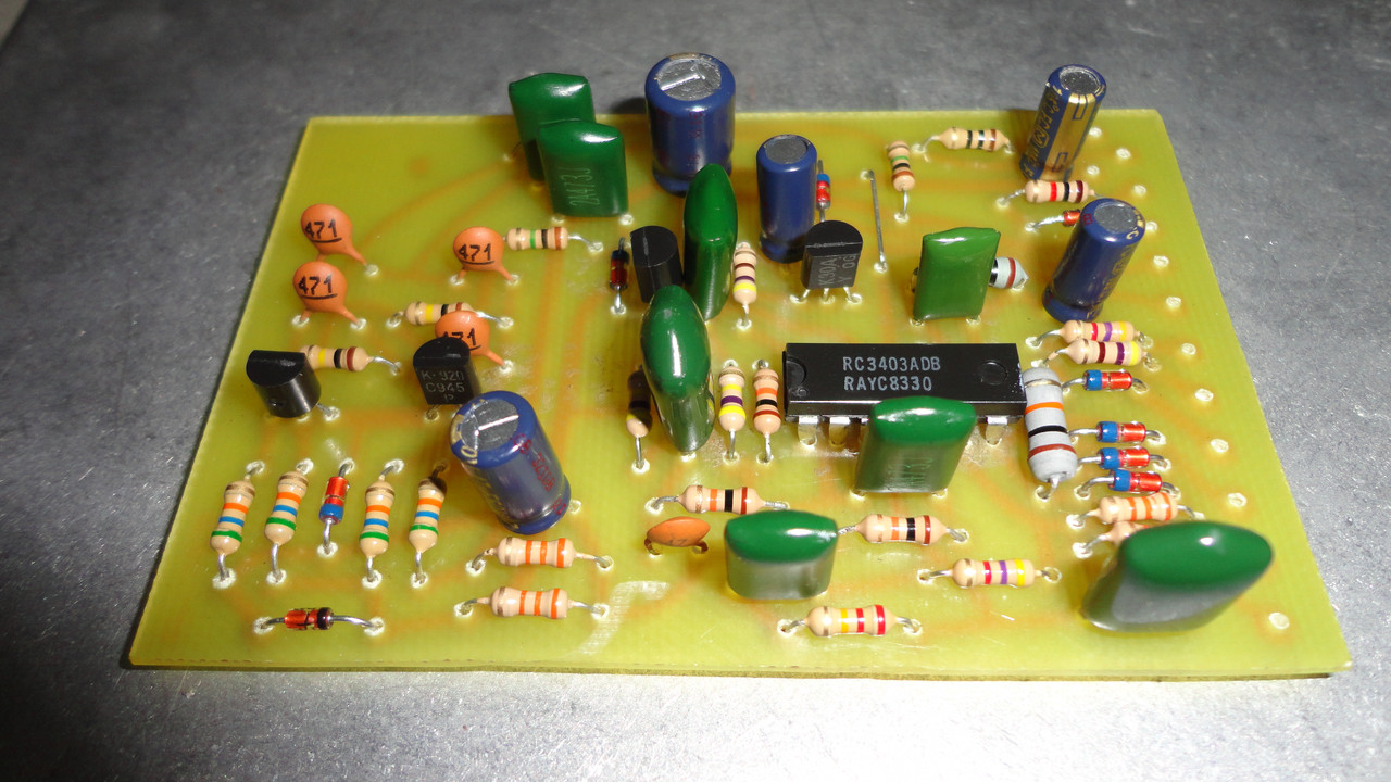
Here a DIY Boss OD-1 I made before have an original, with Xircon film capacitors and Panasonic electrolytics:
Last edited by Old_Iron on Tue Oct 06, 2026 5:34 am, edited 4 times in total.
Re: Re: Boss DM-2 pcb variants
Edited to correct a mistake.Pepe wrote: ↑Mon Oct 05, 2026 9:30 pmSorry, but that is not quite correct. The input may be 9V, but what's going on inside a complex circuit is a completely different thing. Capacitors always need a safety margin. It is safe to use a higher voltage rating, such as 25V, etc. Capacitors of low capacitance values, such as 1µF electrolytic capacitors, seldom come with a voltage rating of lower than 50V. The 0.22µF capacitors inside my early-'70s Jen Cry Baby have a voltage rating of 250V (others still have 160V) for a reason - although powered with a 9V battery.
Laurie can surely shed some light on this topic, as this is part of what he studied at the university.
You are right Pepe. I was making a huge confusion mixing film capacitors with electrolytics.
Boss uses low voltage electrolytics (even 10V.), but uses 50V. metal film caps.
Sorry, I edited the post to correct the info.
-
laurie

- Posts: 2440
- Joined: Fri Aug 17, 2018 2:07 am
- Location: Canada
- SBZ: Multi Platinum
- Bossarea: Multi Platinum
Re: Re: Boss DM-2 pcb variants
In a Boss compact pedal, this should be simple. But it isn't.
Under normal use, a PSA pedal will never see more than 9.6VDC, and an ACA pedal will never see more than about 12 or 13VDC.
If a pedal has an 11V Zener protection diode, the voltage in the pedal is clamped at 11VDC.
If the pedal doesn't have a protection Zener, then with the incorrect power supply the pedal can be exposed to whatever the power supply is putting out.
So. How to decide what voltage capacitor to use? Rule of thumb - 25V is OK.
Why are some caps rated at much more than 25V? All capacitors are not created equal. They are not pure capacitances - they have inductance and resistance, and different physical configurations and dielectrics have varying frequency and impulse responses. So, as an example, a 250VDC poly 0.1uF capacitor is much more musical than a 25VDC ceramic 0.1uF capacitor.
So engineers select capacitors that work best in the particular spot in the circuit. Except ... one example (there are others) ... early pedals that used 1uF electrolytic capacitors in the signal path. These aren't optimal for audio and are often replaced these days by poly equivalents.
Re: Re: Boss DM-2 pcb variants
Thanks for the photo and the brand recommendation! I had been informed about it is 473 and Panasonic, my source was wrong then. Now I won't need to spend hours searching for Panasonic capacitorsOld_Iron wrote: ↑Tue Oct 06, 2026 1:25 amThe original film capacitor Boss used in the DM-2 was made by Yamato.bencuri wrote: ↑Mon Oct 05, 2026 9:59 pmI know but for the component sizes it would be a useful info. It is easier to solder it if it fits properly, and also for authenticity, and it also tells about the tolerance. As I remember there were 2 types that Panasonic manufactured from those green capacitors that are in the Boss DM-2, and the code is there on the capacitors. Those green capacitors are the most problematic parts to obtain from here where I am, and though I have a big stock of the same type of capacitors manufactured by Siemens, I want to put the green ones on the board first because when testing circuits I noticed capacitors are the particular kind of stuff where type variations can influence the sound noticeably
At their side is printed the capacitance, like 473K = 47000pF = 47nF, Yamato's logo (a "Y" inside a circle) and the characters "1H".
Any capacitance value at 50V. will fit at it's place on the pcb.
A suggestion for you. A good replacement for those Yamatos would be Xircon "greenies", they are made in Japan and looks like the old type Boss used at the beguining. You may find them online at Mouser Electronics.
Here a DIY Boss OD-1 I made before have an original, with Xircon film capacitors and Panasonic electrolytics:

Now that 50V is confirmed I can be confident about that I marked the holes correctly, because they match that lead distance those capacitors have according to the info that I found. So very likely the holes for the other components were marked correctly, too.
The only problem is only 100V ones are available nearby, of course the lead distance on them is more. Will try if I can squeeze one into the place available, if I cannot keep the leads short enough I will order the ones from Mouser. 50V green capacitors are totally missing from the selection in the area where I am. There are none like that on Aliexpress either.
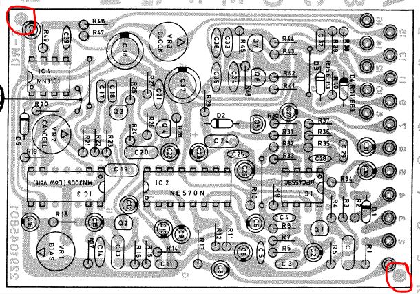
Let me ask about the securing of the board in the housing as well. It is the first pedal that I am building, I am not very familiar with fixing methods for boards, and I was kinda worried when I noticed that I forgot to leave space for screws on my board. But then checking your photos it seemed to me the board is not fixed in the original, but there are ribs or what cast into the metal that seem to function as spacers, and the board is secured between the backplate and those ribs. Is this correct? Why I am confused is because I wouldn't have chosen such a design myself. I would have been worried about the board moving and something breaking off. And I also noticed that on the version 1 board (MN3005 chip) there are two small holes at opposite corners of the board. Are those holes for fixing screws? Those spots are also marked on the image of the board in the service manual, but there they appear as two circle shaped copper dots not holes. What the heck are those? On the schematic they don't appear (like routes or grounding points).
This is what I mean:
Re: Re: Boss DM-2 pcb variants
There isn't any pcb fixing in Boss compact line pedals.bencuri wrote: ↑Wed Oct 07, 2026 4:30 amLet me ask about the securing of the board in the housing as well. It is the first pedal that I am building, I am not very familiar with fixing methods for boards, and I was kinda worried when I noticed that I forgot to leave space for screws on my board. But then checking your photos it seemed to me the board is not fixed in the original, but there are ribs or what cast into the metal that seem to function as spacers, and the board is secured between the backplate and those ribs. Is this correct? Why I am confused is because I wouldn't have chosen such a design myself. I would have been worried about the board moving and something breaking off. And I also noticed that on the version 1 board (MN3005 chip) there are two small holes at opposite corners of the board. Are those holes for fixing screws? Those spots are also marked on the image of the board in the service manual, but there they appear as two circle shaped copper dots not holes. What the heck are those? On the schematic they don't appear (like routes or grounding points).
You can improvise one, but in the original the pcb is just held by the many wires inside the case pressing up against the components side and the back plate with the isolation plastic sheet pressing down the solder side.
One question, do you know that in order to make the effect work like in the original you'll have to adjust those trimpots? (VR1, VR2 and VR3)
How do you intend to do that?
Re: Boss DM-2 pcb variants
I want to do that in the way that is described in the service manual. However, it reminds me to ask: what trimpots would you recommend for this? The info on the 3 trimpots is also totally missing from the manual. Are they single or multi turn, for example?